Verification of PAUT, TOFD Specimen (R3)
Section titled “Verification of PAUT, TOFD Specimen (R3)”Introduction to Ultrasound
Section titled “Introduction to Ultrasound”- Ultrasound
- 1. Phased Array Ultrasonic Testing (PAUT): PAUT technology represents a significant advancement over conventional single-element ultrasonic testing (UT).
- The conventional single-element UT method detects defects by processing transmitted and received signals through a single electronic sensor, which limits the results to a one-dimensional representation.
- In contrast, PAUT builds upon the fundamental principles of UT but utilizes an array of sensors to transmit and receive multiple signals simultaneously. This capability allows the system to generate detailed, two-dimensional cross-sectional images.
- Analogy: The principle is similar to throwing a stone into a pool of water; the resulting ripples propagate outward and reflect back upon encountering an obstacle or reflecting surface.
The Test Piece
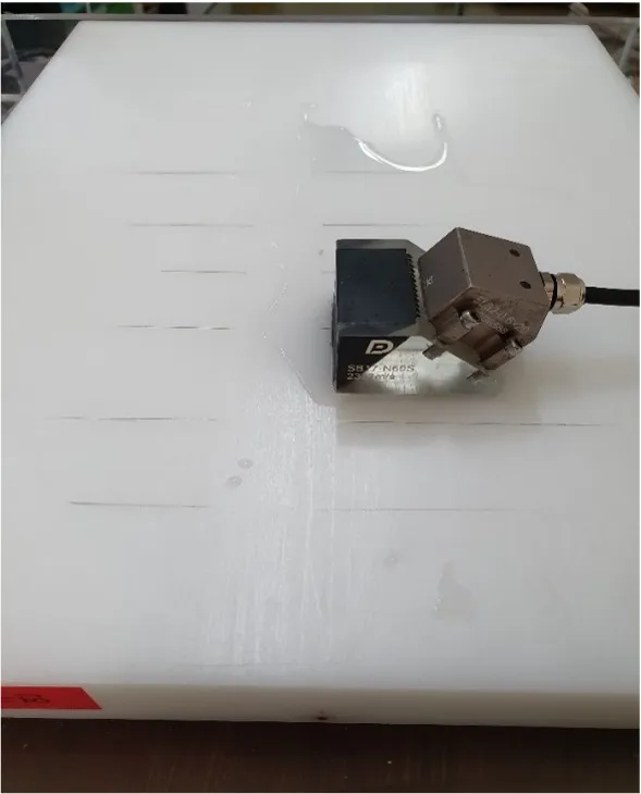
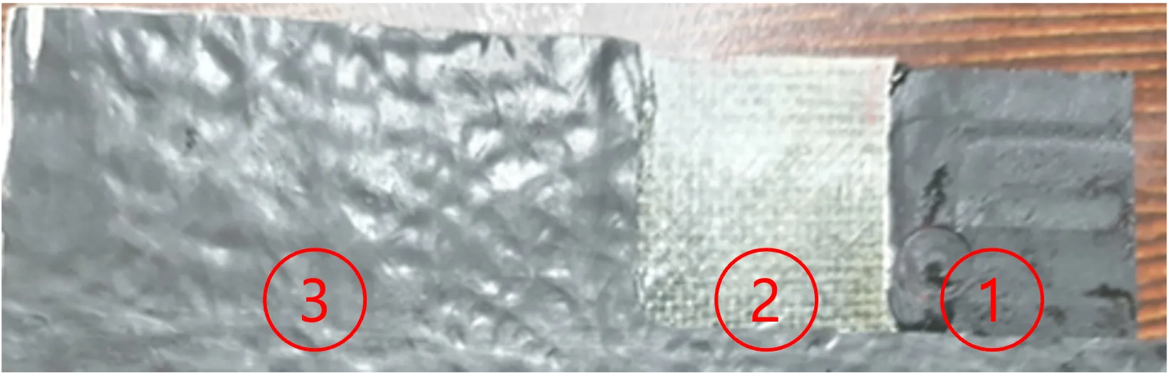
Section titled “The Test Piece”- The primary objective was to observe and verify how the DEEPSOUND R3 measures the specific defect locations marked as 1, 2, and 3.
 < Top Surface >
 < Back Surface >
-
Material: Rectangular PVC
-
Thickness: 29.75 mm
-
Numbered Defect Locations (Measured from the top surface):
- 9.00 mm
- 15.00 mm
- 22.50 mm
< Side View >
- Testing Equipment Used:
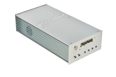
- Main Unit: DEEPSOUND R3 (DEEPSOUND)
- Probe (Sensor): 2.25~5L32 - N45~60S
- Scanner (Encoder)
Defect Measurements
Section titled “Defect Measurements”Defect #1 PAUT Image
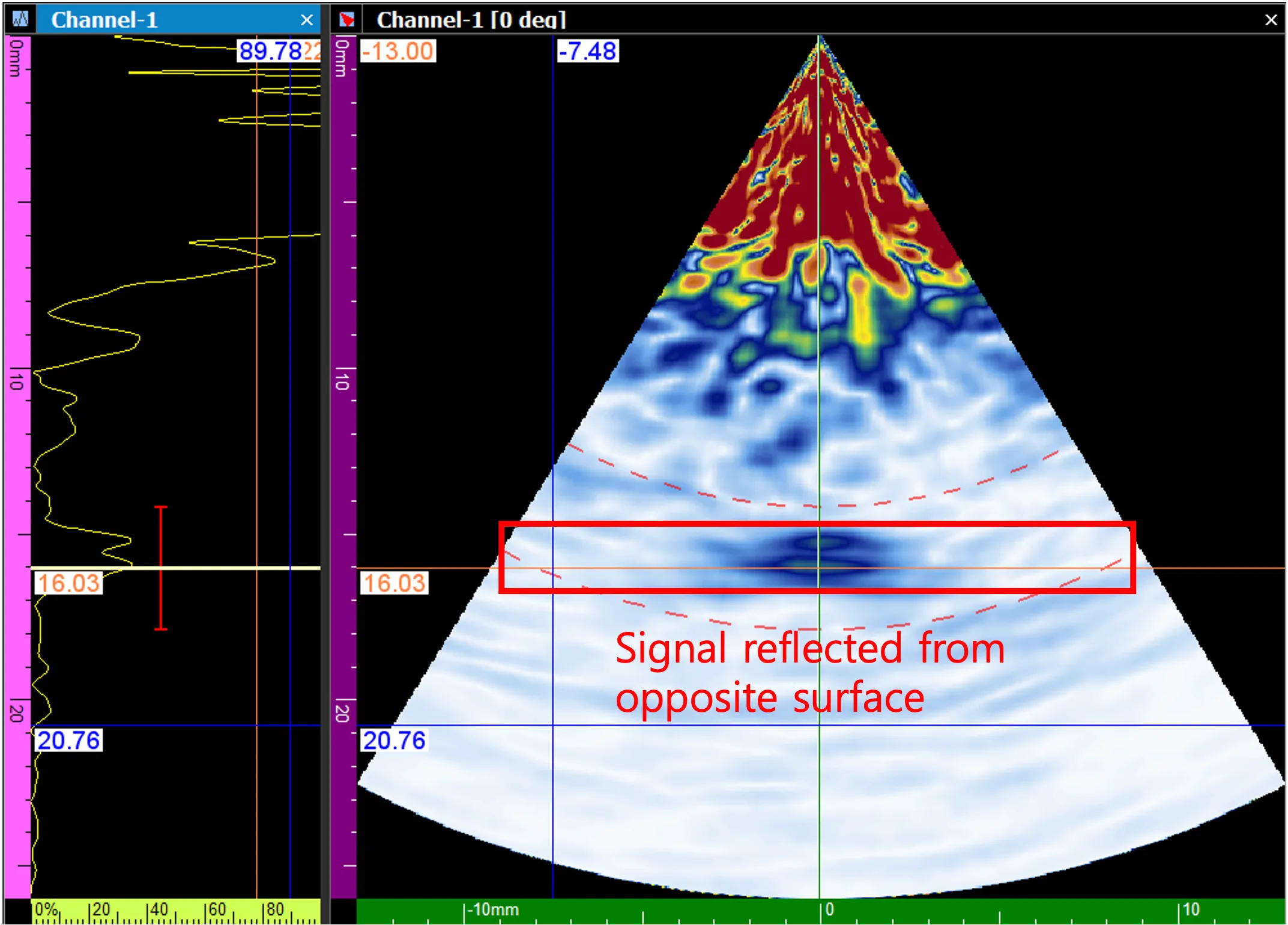
Section titled “Defect #1 PAUT Image”- During the measurement of defect #1, the flaw was detected at a depth of 8.7 mm, resulting in a marginal error of 0.3 mm compared to its actual location.
| Category | Actual Location | Detected Location | Difference |
|---|---|---|---|
| Bottom Surface | 29.75 mm | 29.60 mm | 0.15 mm |
| Top Surface | 9.00 mm | 8.70 mm | 0.30 mm |
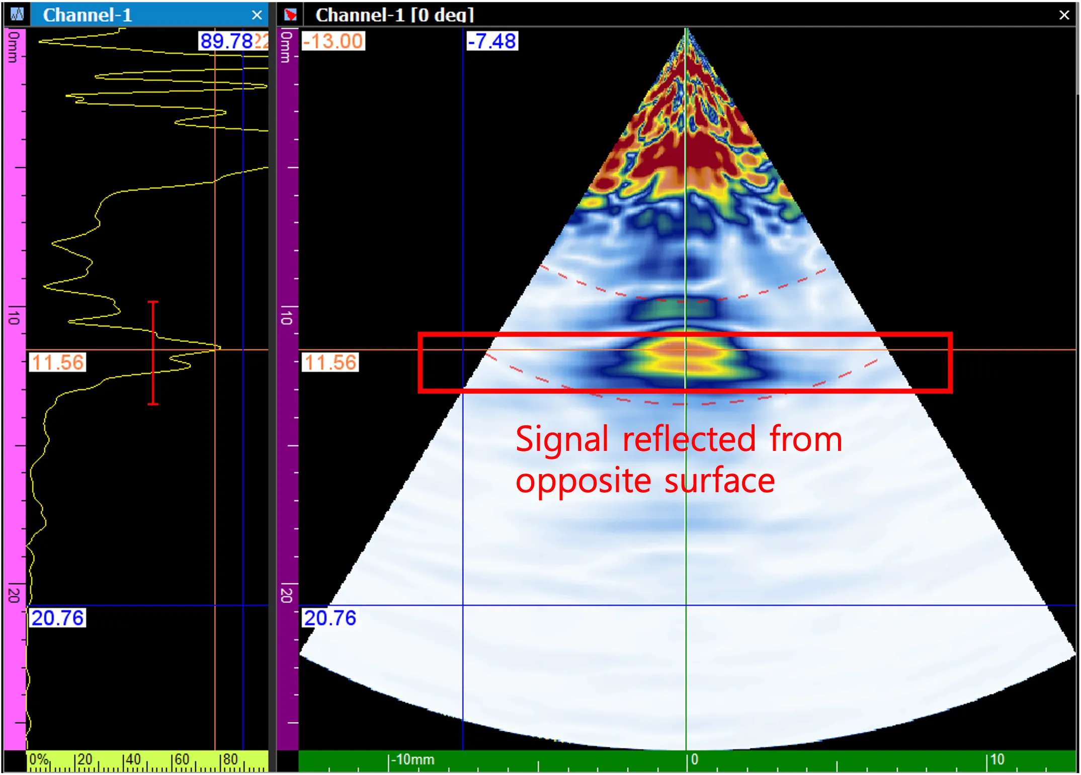
Defect #2 PAUT Image
Section titled “Defect #2 PAUT Image”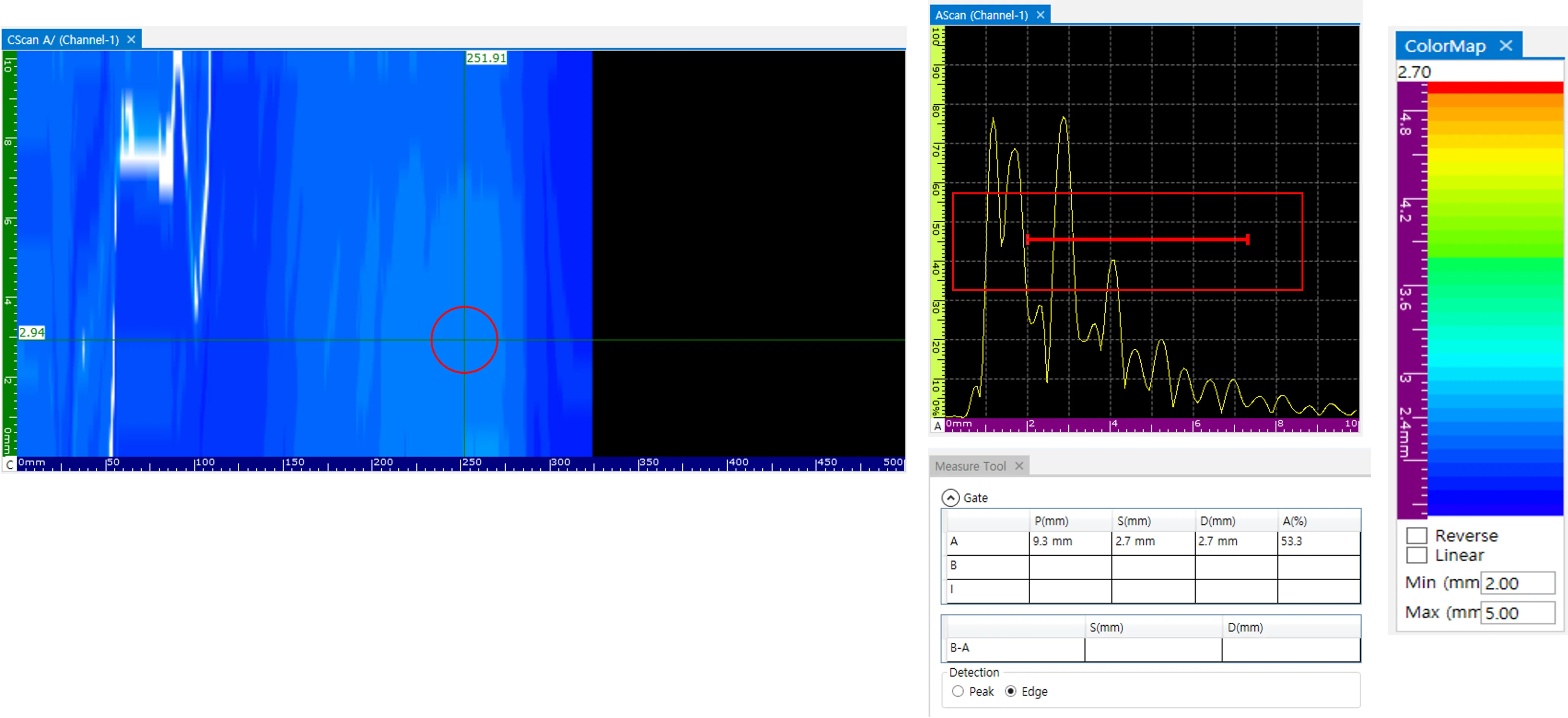
| Category | Actual Location | Detected Location | Difference |
|---|---|---|---|
| Bottom Surface | 29.75 mm | 29.60 mm | 0.15 mm |
| Top Surface | 15.00 mm | 15.90 mm | 0.90 mm |
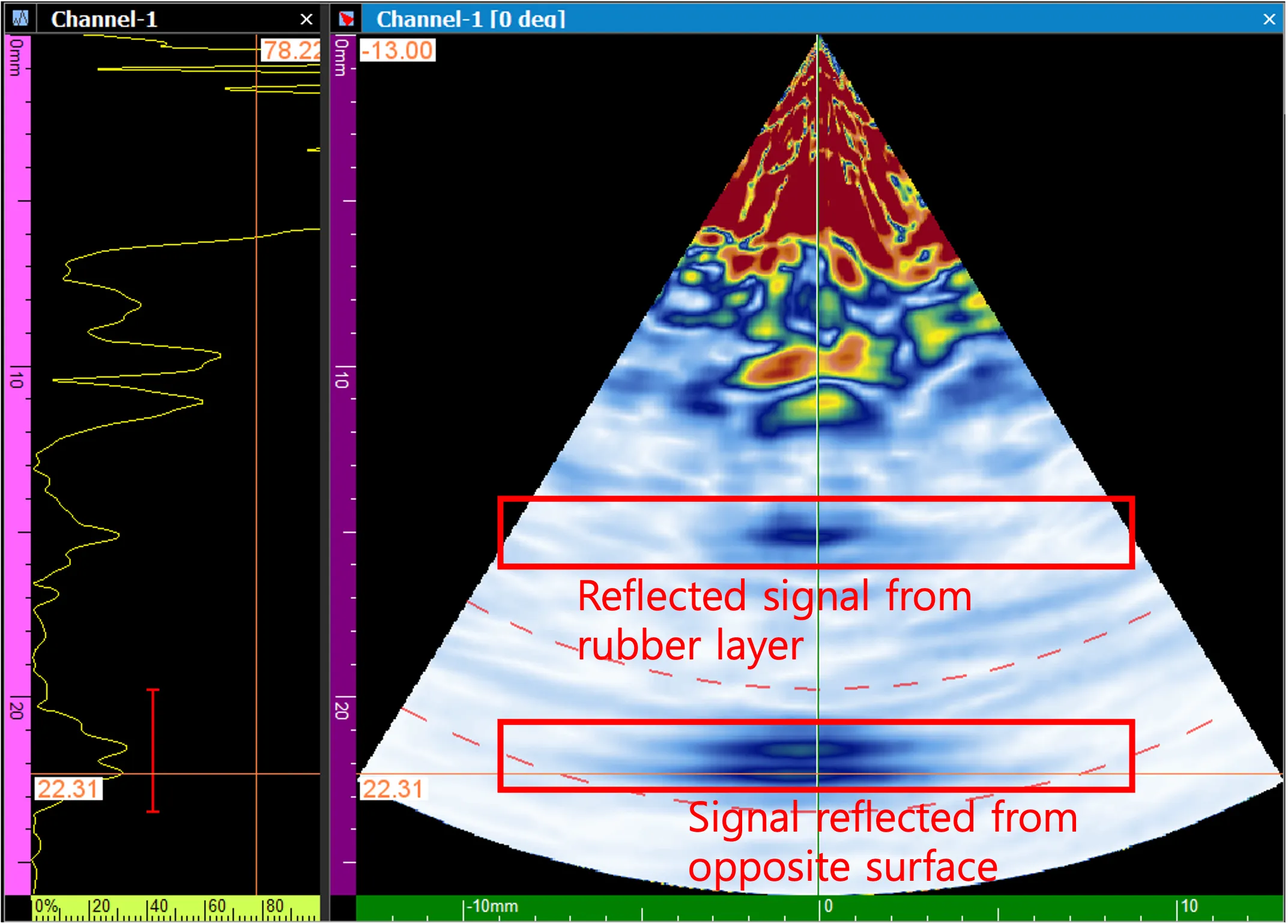
Defect #3 PAUT Image
Section titled “Defect #3 PAUT Image”- During the measurement of defect #3, the flaw was detected at a depth of 23.00 mm, resulting in a marginal error of 0.5 mm compared to its actual location.
| Category | Actual Location | Detected Location | Difference |
|---|---|---|---|
| Bottom Surface | 29.75 mm | 29.60 mm | 0.15 mm |
| Top Surface | 22.50 mm | 23.00 mm | 0.50 mm |
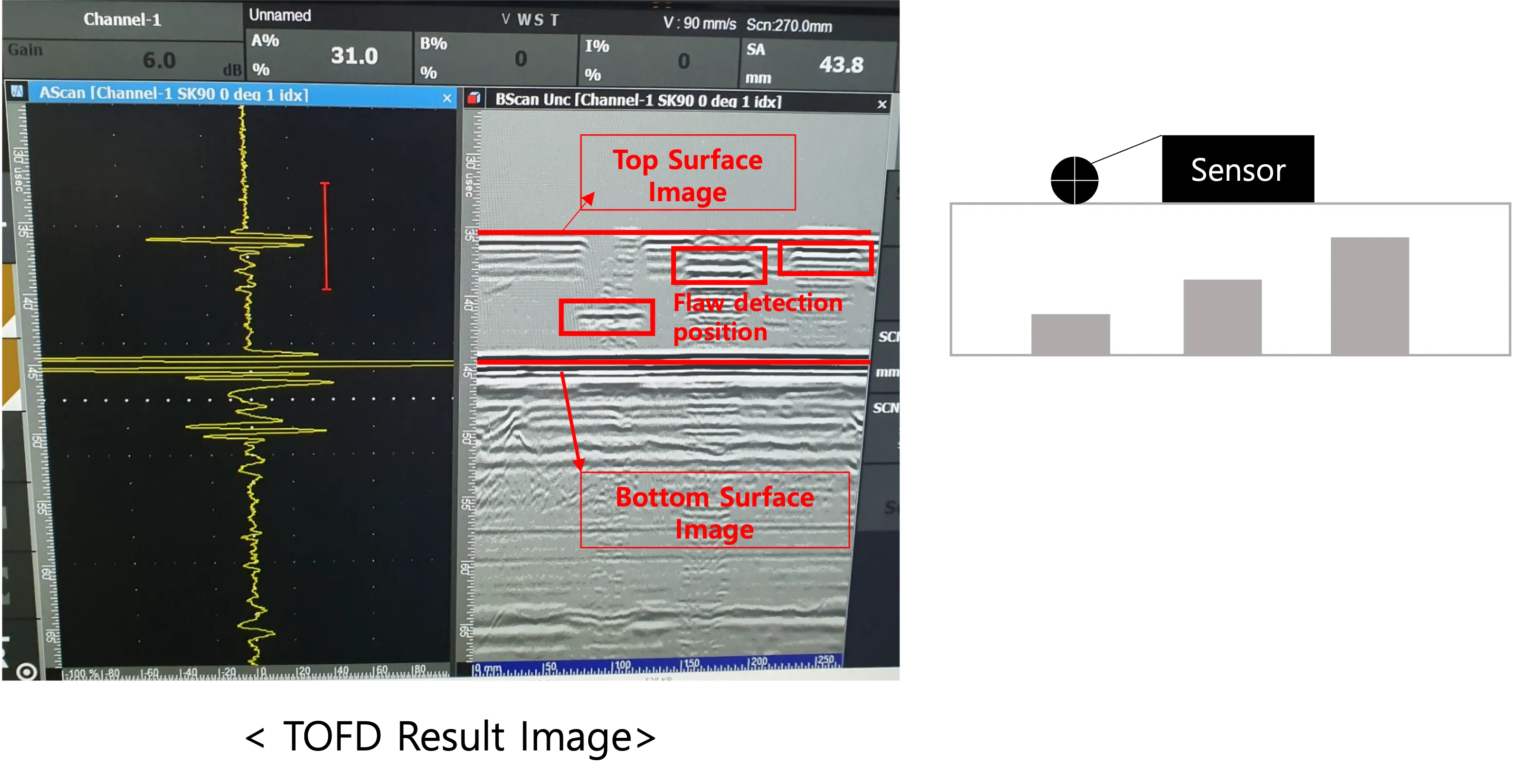
Defect TOFD Image
Section titled “Defect TOFD Image”- The DEEPSOUND system is also fully capable of detecting flaws using Time of Flight Diffraction (TOFD).
-
< Sensor Positions >
-
1. Overview: TOFD is an advanced detection method that utilizes a scanner equipped with dedicated single-element ultrasonic probes on either side of the weld or defect area—one strictly for transmitting and the other strictly for receiving.
-
Advantages: The primary advantage of TOFD is its exceptional accuracy in measuring the precise length and vertical location (depth) of defects. Furthermore, it is highly efficient during field inspections due to its rapid data processing speeds.
Conclusion
Section titled “Conclusion”-
- Currently, comprehensive flaw detection in PVC pipes is optimized by formally employing a combination of both PAUT and TOFD methods.
-
- For relatively thin piping systems (typically those with a thickness of less than 5 mm), TOFD is primarily utilized. For all other standard or thicker cases, a synergistic approach employing both methods is highly recommended.
-
- During the flaw detection measurements on the PVC material, it was successfully verified that the deviation between the detected location and the actual physical location maintains a highly accurate margin of error of less than 1 mm.