PAUT Defect Identification
Section titled “PAUT Defect Identification”Test Specimen and Procedure
Section titled “Test Specimen and Procedure”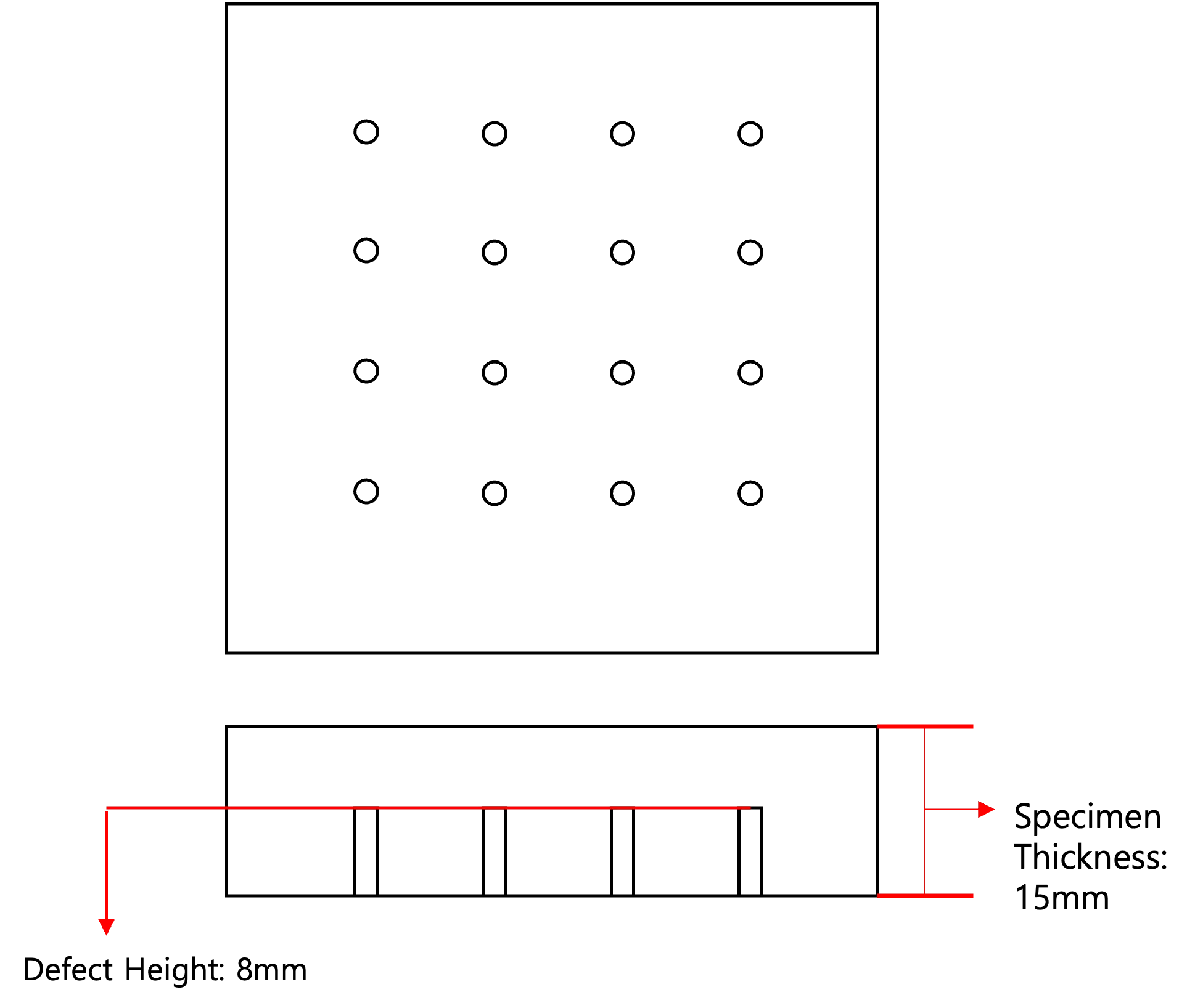
- Test Specimen Data
- Software: DSVision
- Main Unit: DEEPSOUND R3
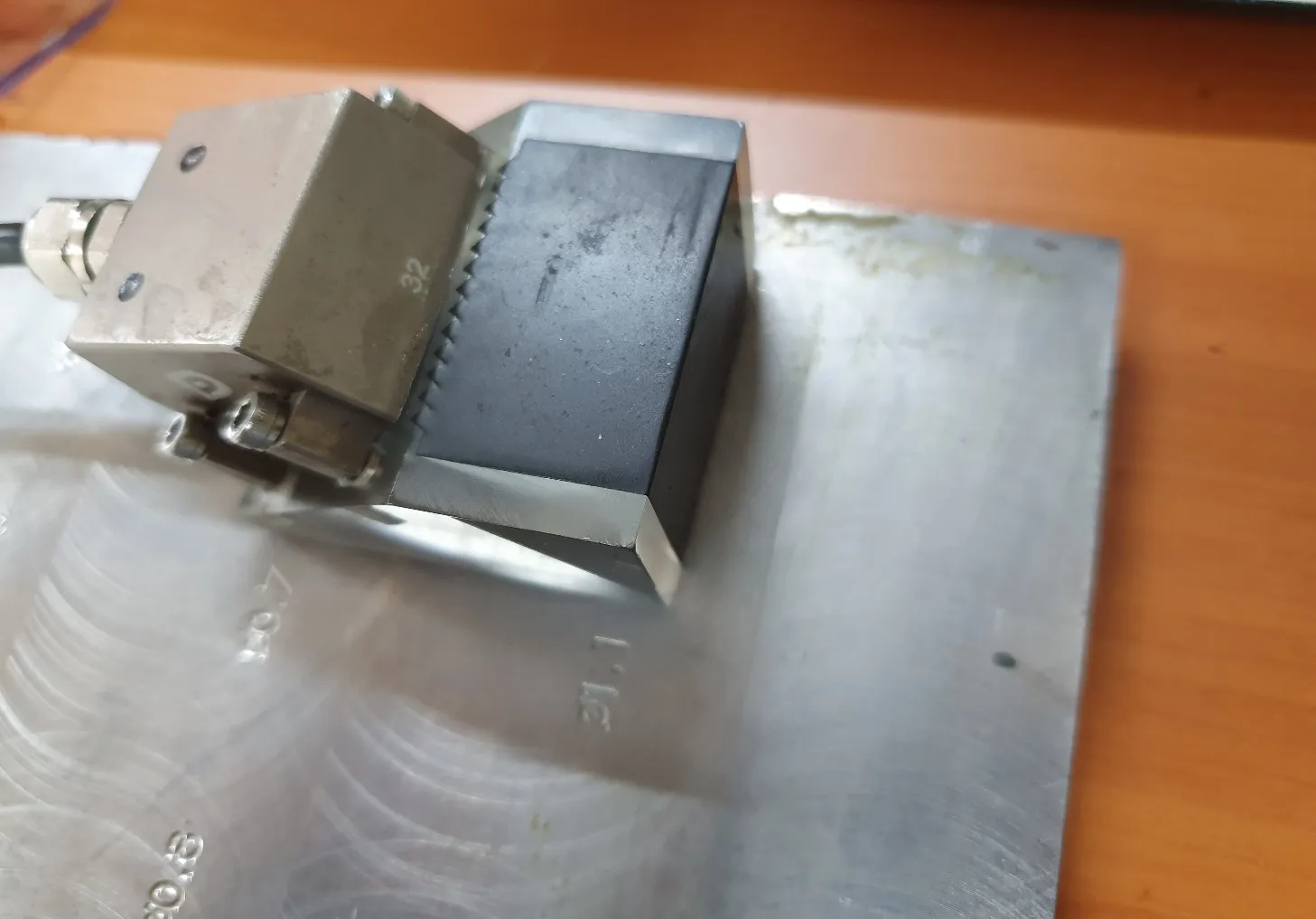
- Probe: 5L32-0.6
- Wedge: SB17-N60S
- Software Settings
- Range: 50 mm
- Voltage: 100 V
- Beam Type: Sectorial
- Digital Frequency: 25 MHz
- Beam Angle: 35 ~ 70 degrees
- Element Count: 16
- TX: 16 / RX: 16
- Focus Position: 6 mm
- Filter: 3 MHz ~ 7 MHz
- Gain Value: 40 dB
Locating Defect in Specimen
Section titled “Locating Defect in Specimen”- Shift the position of the wedge while using the S-scan image as a reference to accurately pinpoint the defect’s location.
- Confirm Defect Location

- Image of the Defect Directly in Front of the Wedge
Interpreting Image Data
Section titled “Interpreting Image Data”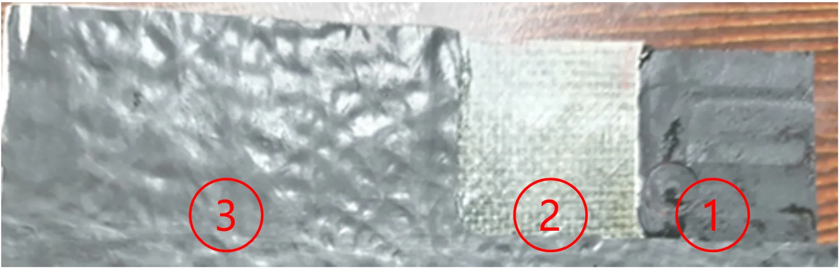
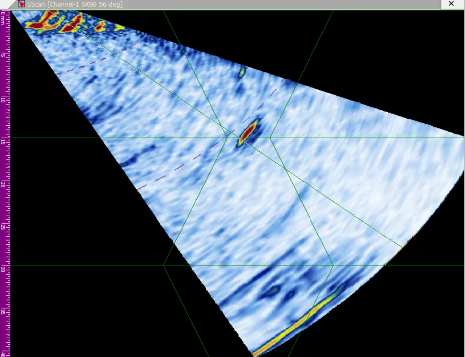
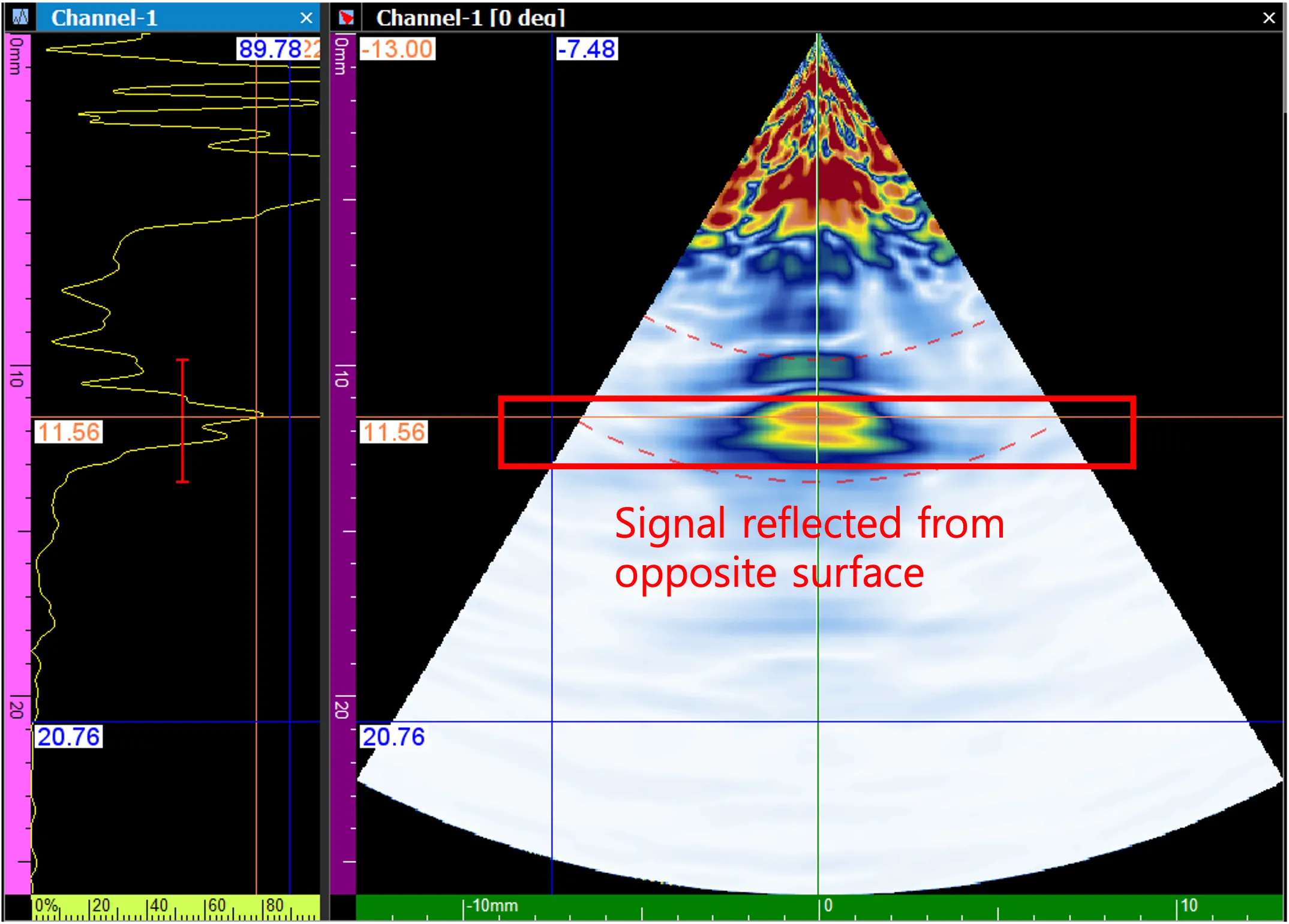
- S-Scan Inspection of the Defect
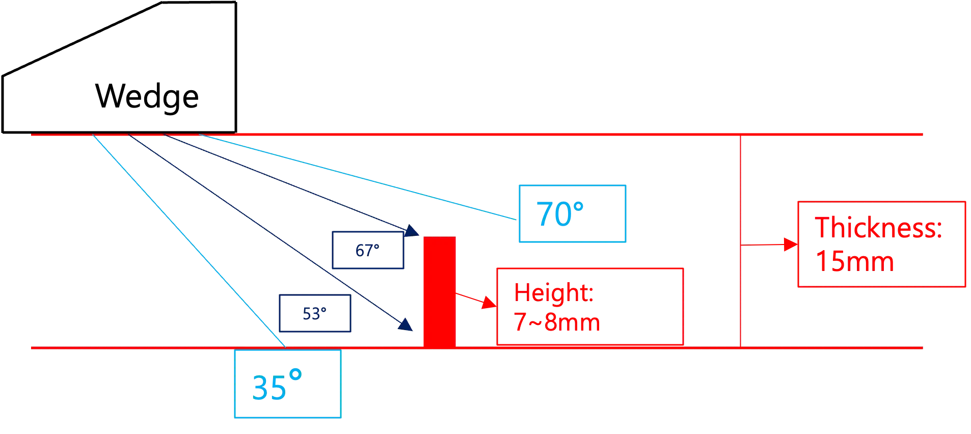
- Diagram of UT Signals Propagating Through the Specimen
| Depth of Detected Upper Portion (mm) | Depth of Detected Lower Portion (mm) |
|---|---|
| 7.26 | 15.03 |
- 1. Because both the thickness of the test piece and the exact height of the defect are known, we can accurately determine which parts of the defect the reflected signals are originating from.
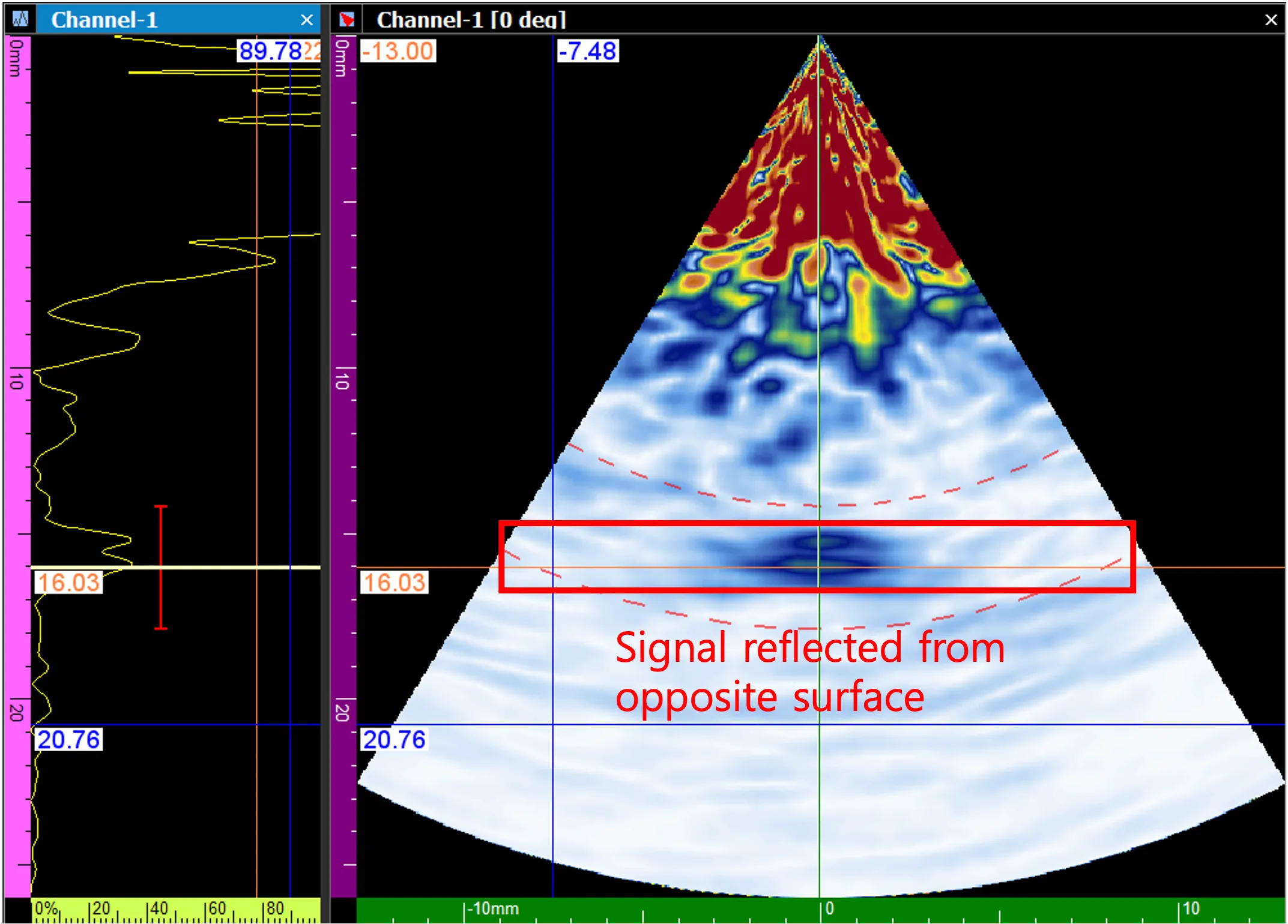
- 2. The receiver gain must be increased to clearly observe the signal reflecting from the defect’s upper portion due to its relatively small surface area. Conversely, the lower portion presents a larger surface area, allowing its reflected signal to be immediately visible.
Shapes of Defects
Section titled “Shapes of Defects”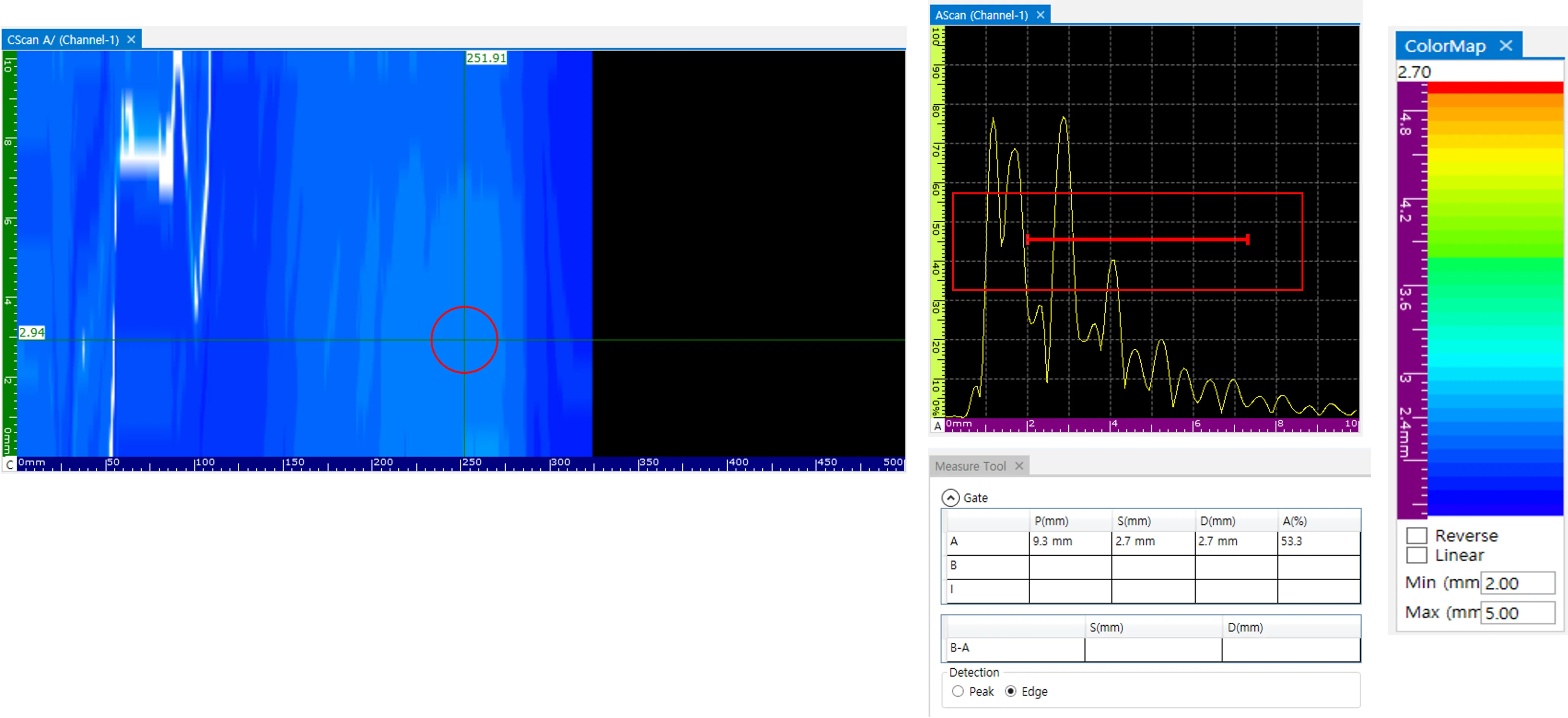
- Drilled Hole Defect Lacking Distinct Reflectors
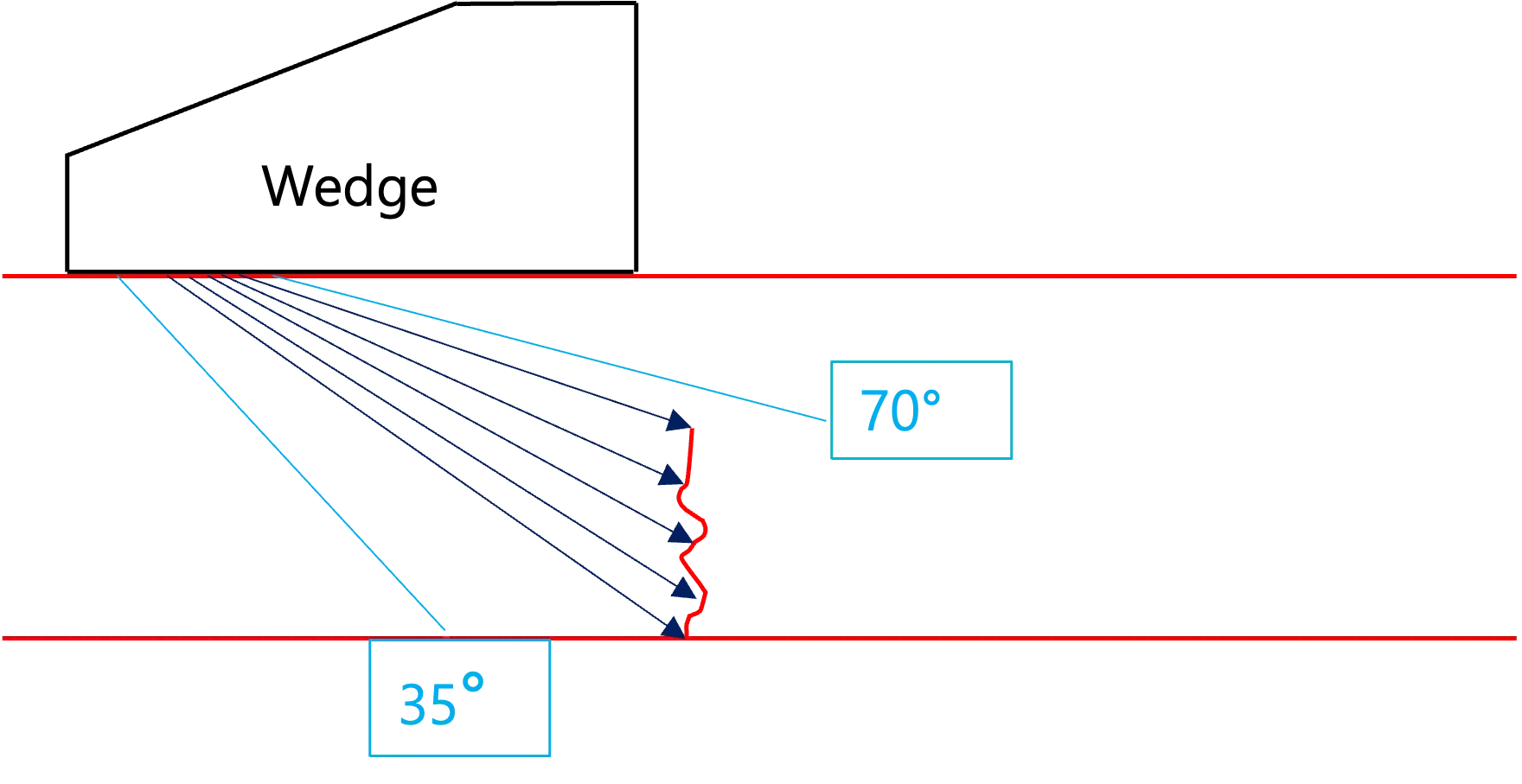
- A Flaw with Distinct Reflectors
-
Corresponding S-Scan Image of a Flaw with Reflectors
-
1. It is inherently difficult to accurately capture the image of a smooth defect that lacks distinct reflectors (like the drilled hole shown above). This is because the probe cannot effectively detect ultrasonic waves that bounce off a smooth surface at a constant angle of reflection away from the transducer.
-
2. Conversely, when a defect features uneven surfaces or distinct reflectors, the ultrasonic waves scatter in multiple directions. Some of these scattered waves invariably return to the receiving sensor, allowing the flaw’s shape to be clearly articulated in the S-scan image.
Conclusion
Section titled “Conclusion”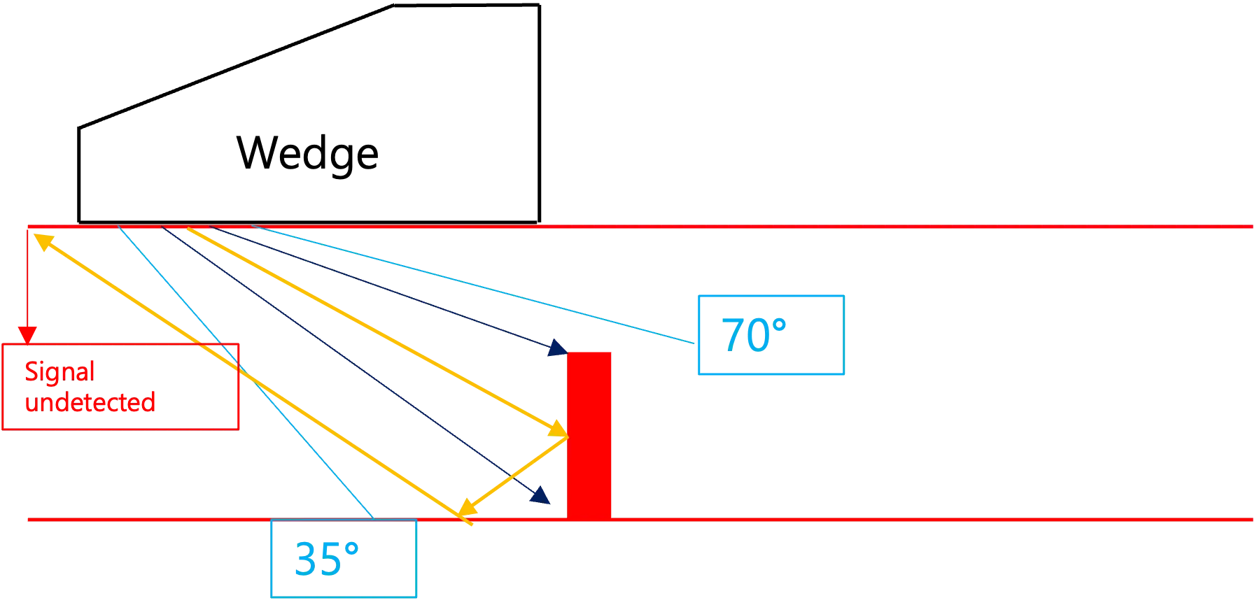
- Artificial Specimen Defect that is Difficult to Identify
-
Naturally Formed Defect that is Easily Identifiable
-
1. Artificial defects meticulously machined into test specimens can be particularly challenging to detect and image accurately due to their smooth geometries. However, naturally formed flaws tend to have highly irregular, multidirectional shapes, which inherently throw off stronger, more consistent reflections back to the probe. Consequently, these naturally occurring defects often present a much more accurate and defined shape within an S-scan image.
-
2. Because Ultrasonic Testing (UT) relies entirely on processing reflected acoustic signals into graphical data, any difficulty encountered when trying to identify the specific shape of a defect is almost always dictated by the inherent physical geometry and orientation of the defect itself.